Noisy Pumps!
These pumps have a rotary
piston action so are inherently quite noisy and subject to
vibration. If mounted incorrectly the vibration can be
transmitted through the fabric of the house and create an
unacceptable background sound, especially in full sun
conditions.
If this over-revving in
bright sun is a new problem it may indicate that the
valves are failing as this reduces the resistance to
revolving as less water will be being pumped, in which
case you may also be able to see the panel temperatures
rising to higher levels than previously due to the
decreased transfer of a slow flow rate. If so then it
might be time to get the pump checked out, which we are
happy to assist you with and you will see notes on that on
this page.
The pumps are designed to
increase speed with the strength of the sun hitting the PV
panel, with the logic that therefore the water panel
should also be creating more heat which needs transferring
faster. This is good, but the pumps can get a bit
over-enthusiastic in direct sun, with a noticable increase
in sound level.

......Recommended Pump
Mounting Method to avoid sound transmittance.
If you have checked the
mounting method is not allowing vibration to conduct to
the fabric and are still bothered by the noise then I have
found a method of capping the peak voltage coming from the
panel to place a cap on the motor's top speed, as this is
when most people notice the noise.
In this maximum power state
the flow rate is probably faster than is really required
anyway.
 Speed
Control ....... Speed
Control .......
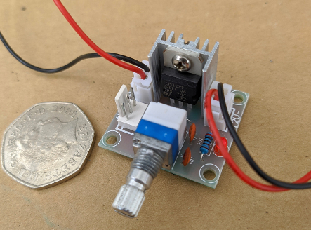
These circuits are available
for around £5 or less on eBay, search for "LM317 Speed
Control" or try this
link: They are very easy to fit, feed the pump power
in to one side and out to the pump on the other side.
The peak voltage can then be
set by ear on a sunny day. From fully clockwise, Turn the
power down until you get an acceptable noise level.
Keep an eye on the water panel temperature to check that the
new flow rate is still enough to shift the heat away to your
tank without the panel boiling.
SolarTwin
Controllers

Newer SolarTwin systems
included a Differential Controller, powered by the PV
panel. Its function is to ensure the pump only runs when
there is heat available in the panel. This controller
delivers improved efficiency versus the early system
whereby the pump runs whenever there is enough light
hitting the PV, irrespective of heat being available.
In this photo the arrows
pointing down at the panel icon at top left of display
indicate the pump has been switched on to capture heat.
The temperature displayed is at the tank top, indicating
the stored water temperature.
We have seen several of
these controllers breaking down after a few years,
usually due to the failure of two key components which
prevents the controller storing sufficient power to run
itself. If you have a faulty controller then contact us
to explore whether it may be repaired.
This Loss of Display fault
is due to a couple of the components on the circuit
board breaking down. Contact us if you'd like us to fix
this, it will require removing the front cover and
sending it to us. Meanwhile the pump can be connected
directly to the PV panel for the few days it will be
away and the pump will run normally during that time,
that is how the original systems were installed before
the controllers were added. This Controller fix is
inexpensive at £23 inc UK postage.
The panel temperature
probes seem to suffer from inaccuracy in some
installations. These are a PT1000 type sensor on a very
long length of co-ax cable so I wonder if fitting a
small capacitor (around 0.1uF) across the two wires as
they enter the controller casing would help avoid
erratic reads. I'd be pleased to hear from anybody who
could try this fix.
Other common faults
include a failing panel temperature probe. Spare sensors
are available on request but they are fitted into the
rear of the panel so replacement involves climbing on
the roof to lift the panel in order to gain access to
the cable entry point.
New controllers are hard
to find, though I do currently some in stock at
£110 each (including three sensors and cabling)
if yours cannot be fixed. They aren't listed in my shop
so email me for availability

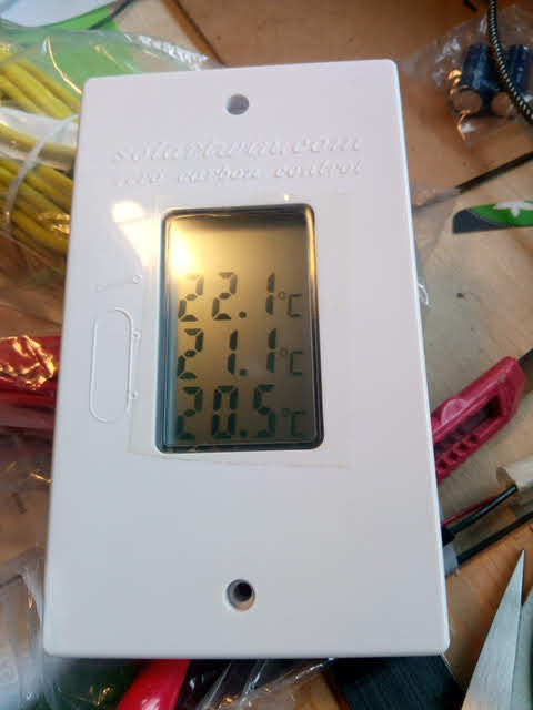
The default display on
these units shows only the temperature of the hot water
tank, measured at the top. There is an alternative display
mode which is useful for setting a system up, whereby all
three probe temperatures are shown on the same screen.
Accessing this is supposed to be by opening the controller
case and pressing UP DOWN and SET buttons together for 30
seconds.
We found this did not
work on our sample, so try the following sequence to
change the display:
1/ Hold down SET and then
press RESET briefly. The display shows "EEP" with "000"
beneath it.
2/ Now press SET once more.
The three temps will show,
the upper one is the panel temp, middle is the tank top
temp and the third is the tank base measurement. On the
unit I tested this also switched the pump on, irrespective
of temperature delta, so is only useful for de-bugging
sensors, not for constant display use.
Return to the default
display by pressing RESET.
I have learned some useful
things about this controller - It doesn't seem to like
being asked to switch when supply voltage is below 7.5V,
although it continues to read and display ok at this low
voltage. A faulty pump with high current draw might cause
the input voltage to drop so try disconnecting one pump
wire to see if that corrects a controller error. The
controller passes whatever the input Voltage is on to the
pump, hence the variable speed.
Similarly, the two
supercapacitors often fail, try unplugging them completely
in case they are pulling the voltage down with a short
circuit. These are replaceable if failed. Finding a
similarly rated part with the same physical dimensions may
prove very hard, in which case the new supercapacitors
might have to be mounted externally but they will work in
that position if necessary.
The controller compares the
panel temp with the tank top temp to decide when to run
the pump (not the tank base as with every other type of
controller!) There is a time delay of 30 seconds or more
before the unit switches the pump after detecting the heat
delta.
The panel probe is a type
PT1000. At room temperature it will have a resistance of
circa 1068 Ohms. The two tank sensors are NTC10K and have
a room temp resistance of around 13k Ohms. If you are
getting implausible readings then checking that the
resistances across the disconnected wires of the sensor is
a good idea. The resistances at different temps can be
found by googling for a sensor chart for that type of
sensor.
On the display : the inward
pointing arrows are shown when the controller has passed
power to the pump. If the tank top exceeds 60 degC and the
panel is less than that temp then the pump is switched on
to export heat and cool the tank. Outward arrows show when
in this state.
Possibly Useful Solartwin reference
documents
Original
Installation Instructions to installers
Solartwin
User Guide
Leaking
Collector Panels
Here in 2023 I am hearing of more and more people reporting
their panel has begun leaking and dripping on to the
roof. So clearly the silicone tubing inside the panel
has a finite life span is starting to fail.
If this happens to you then it isn't a quick fix but here is
some encouraging news from a customer that you may find
helpful:
"
When I spoke to someone in Genfit they said it had
come to their notice that the silicone tubing was
breaking down in older panels. They would have
supplied a new panel for £1000 (plus carriage) but I
thought it would be worth giving it a go so I took
the panel down (first mistake – forgot about the
temperature sensor so broke the cable!). I
tried drilling the rivets but too slow so took a
small angle grinder and took the top of each one
(much quicker but approx. 260 rivets) and then with
a block of wood underneath the rivet, punched out
each of the rivets. I replaced the tubing and
riveted it all back together. Some of the
rivets pulled through but otherwise still held and I
touched up some of the black paint as appropriate.
I
got the sensor and tubing from DiscreteHeat;
Yellow Sensor £18.95, 24m of 16mm Silicone (food
grade) £120 , shipping £15 all plus VAT so cost me
£185 plus a box of rivets out of Screwfix and now
thanks to your help it is running!
Took
some time but I think worth it all and especially
because the design is so simple.
Hope
this might help someone else.
David
"
If
you decide to tackle this rebuild job then contact me
as I should be able to source the tubing (or sensor!)
at a good price, making it even more viable.
Obviously not a simple task but quite
manageable. I might even have a repaired panel
available as an exchange
Here is some information on how to fix that leak I hope it is helpful to you in deciding what action to take. The repair project took me a little over a day to complete.
PV Panels and System Checks 
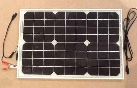
The PV panels used are all 5Watt
and there isn't much to go
wrong with a PV panel, but if you have no power output
then check the wiring carefully before seeking a new
panel, it is much more likely to be a wiring fault than
a panel failure. I have some spare panels if you need
one.
 Slightly confusingly,
SolarTwin used two different specs of 5Watt PV,
nominally 6V and 12V. A quick check of the voltage
across the wires "Open Circuit" ( i.e. disconnected from
the controller and pump) will confirm which you
have. If you measure over 18V then you have the
12V panel, 9V indicates the 6V panel. This is
significant when making the checks described
below. The spec of the PV is shown on the rear of
the panel if you remove it from its mounting. Slightly confusingly,
SolarTwin used two different specs of 5Watt PV,
nominally 6V and 12V. A quick check of the voltage
across the wires "Open Circuit" ( i.e. disconnected from
the controller and pump) will confirm which you
have. If you measure over 18V then you have the
12V panel, 9V indicates the 6V panel. This is
significant when making the checks described
below. The spec of the PV is shown on the rear of
the panel if you remove it from its mounting.
Shown Left is an example of the
Spec Label on a 6V PV panel
If you suspect your PV panel may be
faulty then there are a couple of tests you can carry out.
You will need a digital voltmeter, there are plenty of
suitable models on eBay for little over £5.
STEP 1. On a bright sunny day with the
panel facing the sun - Disconnect one of the wires that
lead from the PV panel to the controller so that no
current can be being drawn by the pump etc.
STEP 2. Switch your voltmeter to the
10Amp setting. (You may need to locate one probe lead to
the 10A socket on the meter for this function)
STEP 3. Place the meter leads on each PV
wire to measure the PV output in a 'dead short'. For
the 12V panel I would expect a reading of 0.25Amp or more
in strong sun. If you are getting much less 0.2Amps then
consider looking for a wiring breakdown before concluding
that the panel is broken. Similarly the 6V panel
should give 0.4Amps or more.
If the problem you identified was the
pump running too slowly or not pumping properly then
reconnect the PV to the controller and remove one lead
from the pump. Now bridge the gap from pump lead to the
controller terminal with the meter probes, so that you are
now measuring the current being drawn by the pump.
A healthy pump will draw between 0.2 and 0.3 Amps to give a
good flow rate. Now try squeezing first the inlet pipe then
the outlet pipe to restrict the flow. You should hear the
pumps note change under the increased flow resistance and
the current will increase on your meter. If the pump note
does not change then the pump may need servicing, please
see my service offer above.
Advanced
Problems and Solutions - Blocked Panel
Circulation
If your pump tests OK but you are still not getting any
hot water circulation then it is time for some more tests
to identify the cause. I will assume you have checked and
rechecked that the pump is primed properly as a build up
of air in the pump is still the most likely cause.
I have seen a few cases recently where a blockage is
preventing circulation. If your pump starts up OK but
stops after a minute or less then it may be trying to push
water against a solid obstruction. A pump with perfect
valves will stop under this resistance, others may still
revolve slowly as the pressure relief valve allows the
pressure to discharge slightly.
Solartwin systems in hard water areas should
have had a water softener fitted but this was not always
the case. This prevents a limescale build up in the panel
and pipework. If you can feel pressure from the pump on
the outlet pipe next to the pump but the temperature of
the panel is very hot then you might suspect there is a
blockage somewhere in the circuit.
This may be confirmed by attaching a garden hose to the
outlet pipe to see if mains water pressure can push water
through the circuit. With just a trickle of mains flow
applied you may feel the hose being pushed off as the
pressure builds, whereas a healthy system will allow that
flow and the pressure remains low.

So you have concluded there is a blockage? Familiarise
yourself with the above circuit diagram, then here is the
order I would tackle this:
1/ Check the pipes for any kinks. With the pump running,
Cut or Remove the pipe leading from the Collector Panel at
the point it connects to the top of the water tank
(probably on the 1 inch pipe above the tank). If you've
enough slack then bending the white pipe over once and
taping the bend by the cut will seal it. Afterwards you
can discard the short offcut and refit the longer pipe to
avoid having an extra joint. Use a bucket to catch water
from the white pipe..
2/ Is the pump pushing water out the soft white hose? If
a steady flow is observed there is no blockage. If not
then the most likely site for a blockage is in this pipe.
This is because the panel itself contains pipe that is a
much larger bore so any blockage will pass through until
it hits the narrower white return pipe (6mm ID) .
3/ If it is blocked then try back flushing this pipe with
a hose, after having removed the pipe at the point it
leaves the pump. This allows the pressure to blow off
whereas the pump would block it.
People have reported success using a good bike pump and
Schrader valve blowing air to shift the obstruction (this
avoids spillage issues in your loft if it works. As the
pipe is soft silicone it will inflate slightly under air
pressure and that may be enough to shift the blockage,
albeit back into the panel. If it blocks again try blowing
through in the direction of flow. Of course, if you can
access the pipes on the roof then it would be best to
remove them from the panel so any blockage is blown out,
but most prefer to work inside for good safety reasons!
If you have hard water and can see that limescale is a
likely cause then filling the pipe system (on a dull day!)
with descaler or vinegar for 24 hours or more would be a
good idea, but this can only be done once the blockage is
moved. I am guessing that it will take 3 or 4 litres to
fill the system from between the pump outlet to the point
the pipe joins the hot tank, so both pipes need to be
disconnected during that soak exercise.
If this proves useful then please share your experience
with me for the benefit of others in the future.
go
to HOMEPAGE or here
to go to
SOLAR FAQ page
Q&A or here for
INSTALLATION
GUIDE
|